Our first step was to design an arm. Our team decided to construct a protective metal shield for our motor and attach a chain to create a pulley system. After the design stage, we started by connecting gear chains to our claw with a servo. Afterwards, we attached another servo to the end of the arm to allow movement in the claw. Eventually, our servos were not ordered by specs so with a little help from the organization team, the arm base team organized the servos to continue working on the arm base properly. After attaching a few more rods, our base was done. All we needed to do now was to attach the claw when it was finalized and attach the arm base to our main chassis. We attached the arm base in the middle of our main chassis.
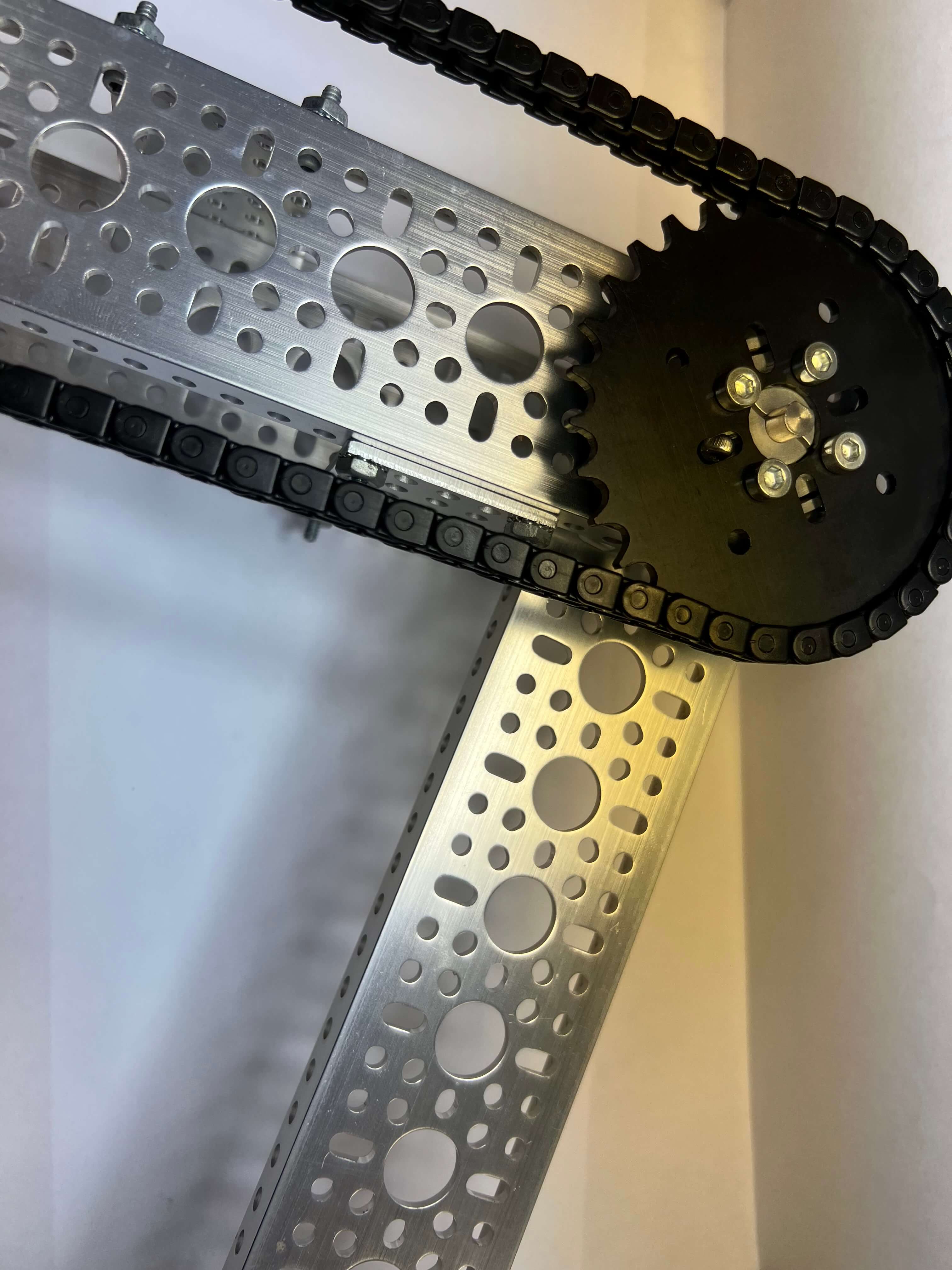
Arm Base Part
A section of the arm base.
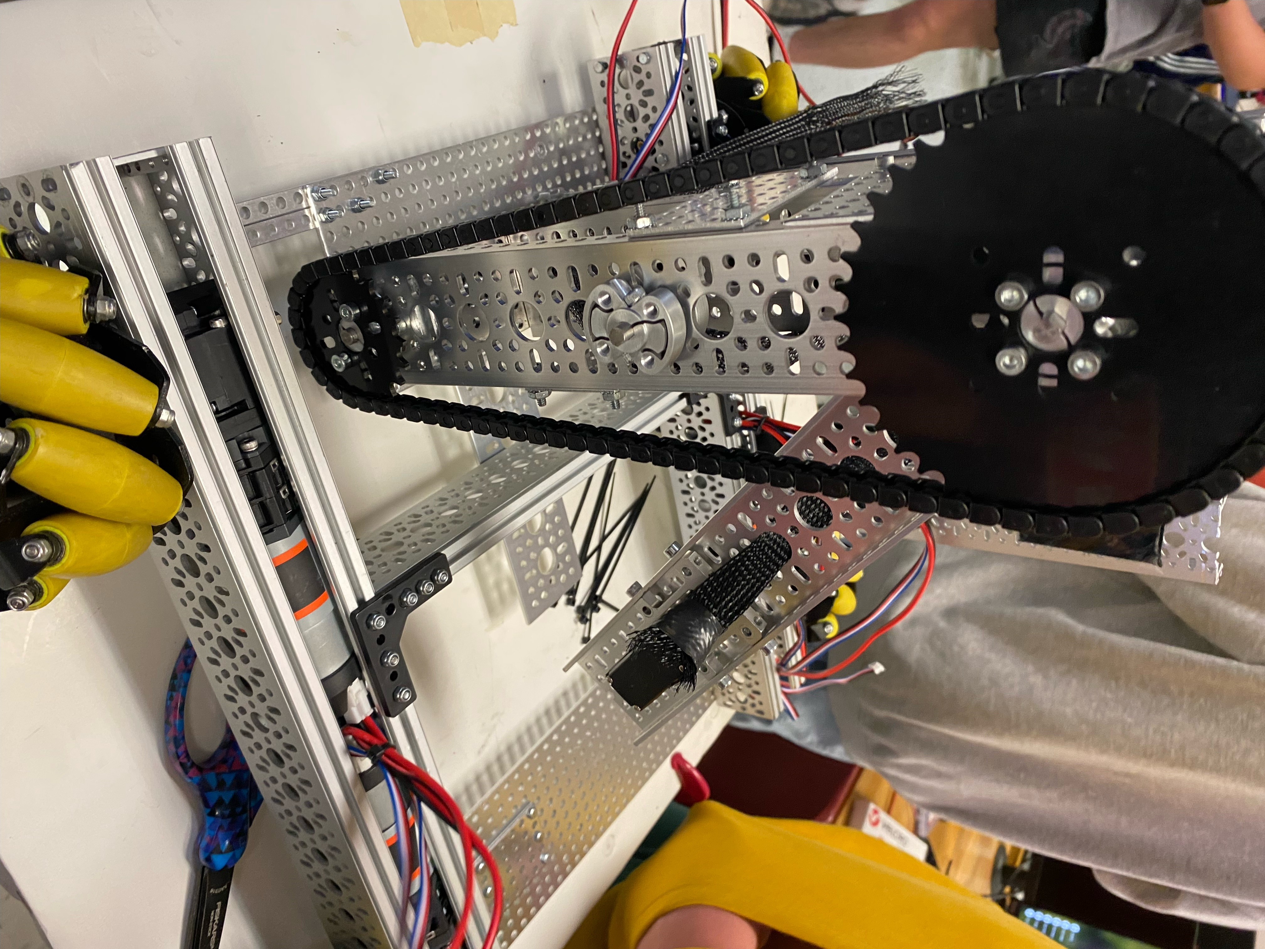
Arm Base Full
The entire arm base.
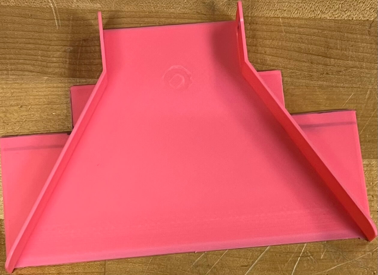
1st Scoop
1st Scoop design.
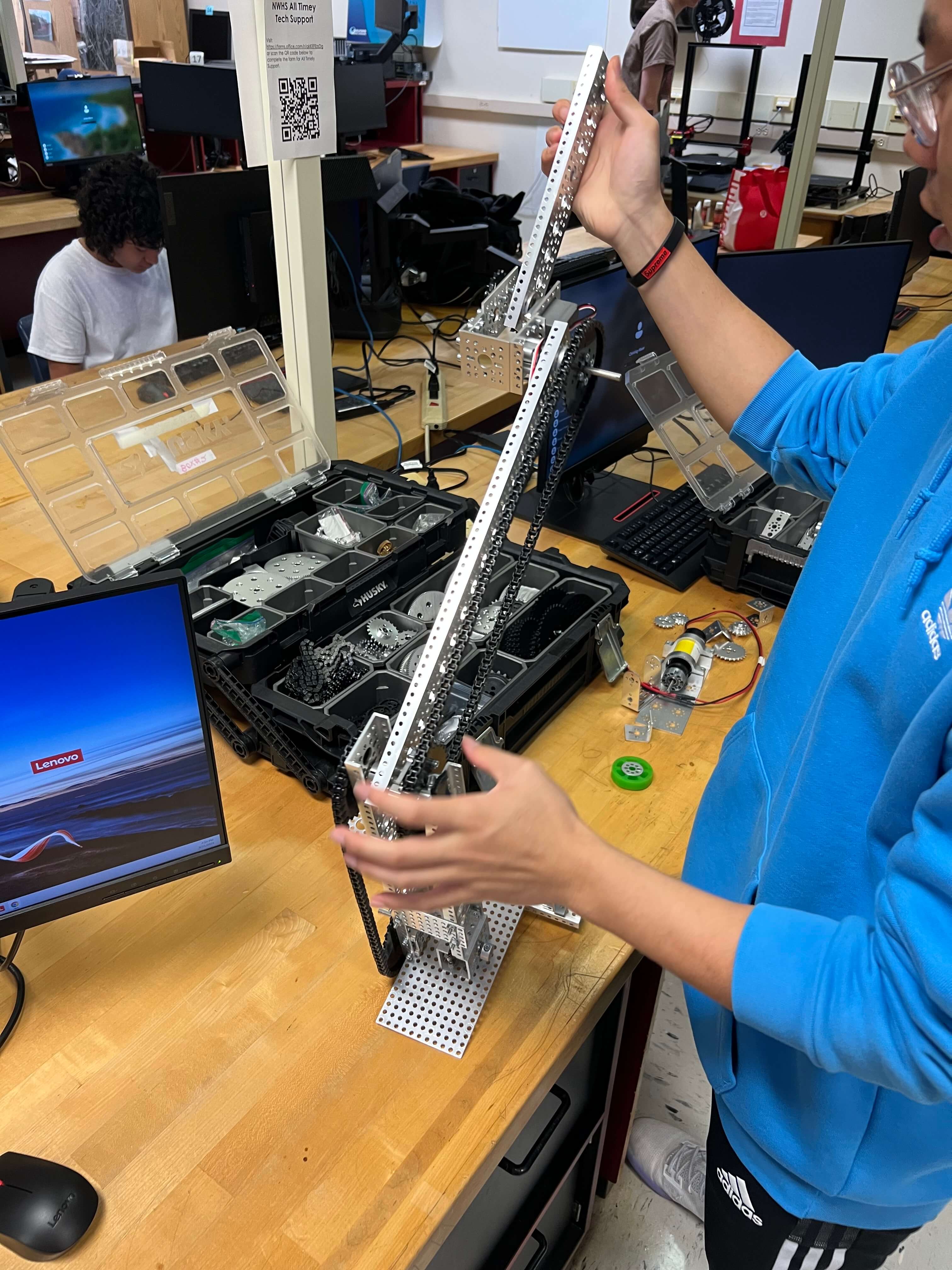
Assembly
Assembling the arm base onto the main chassis.
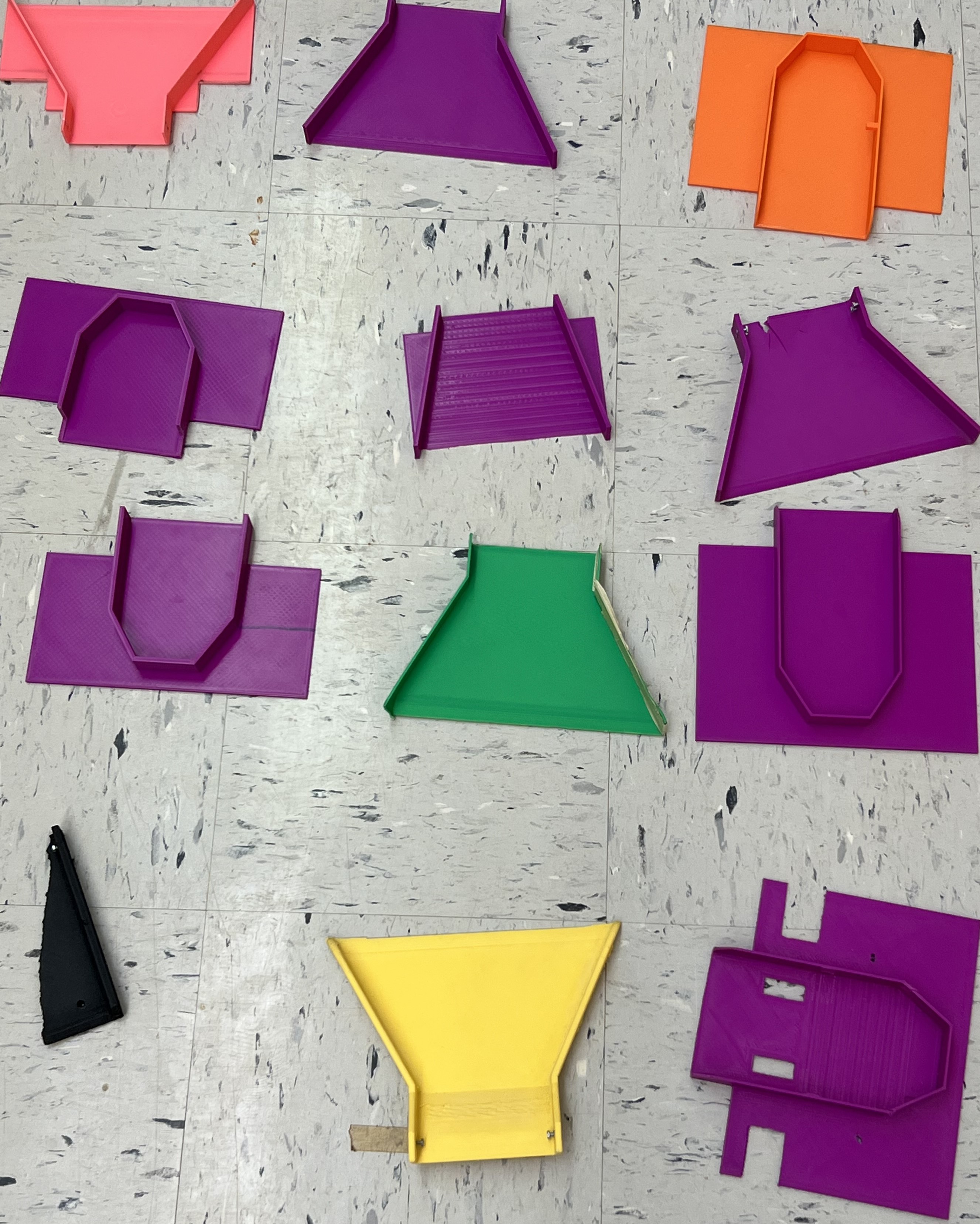
Scoop Collage
All unused scoop designs and a part of our used scoop design.
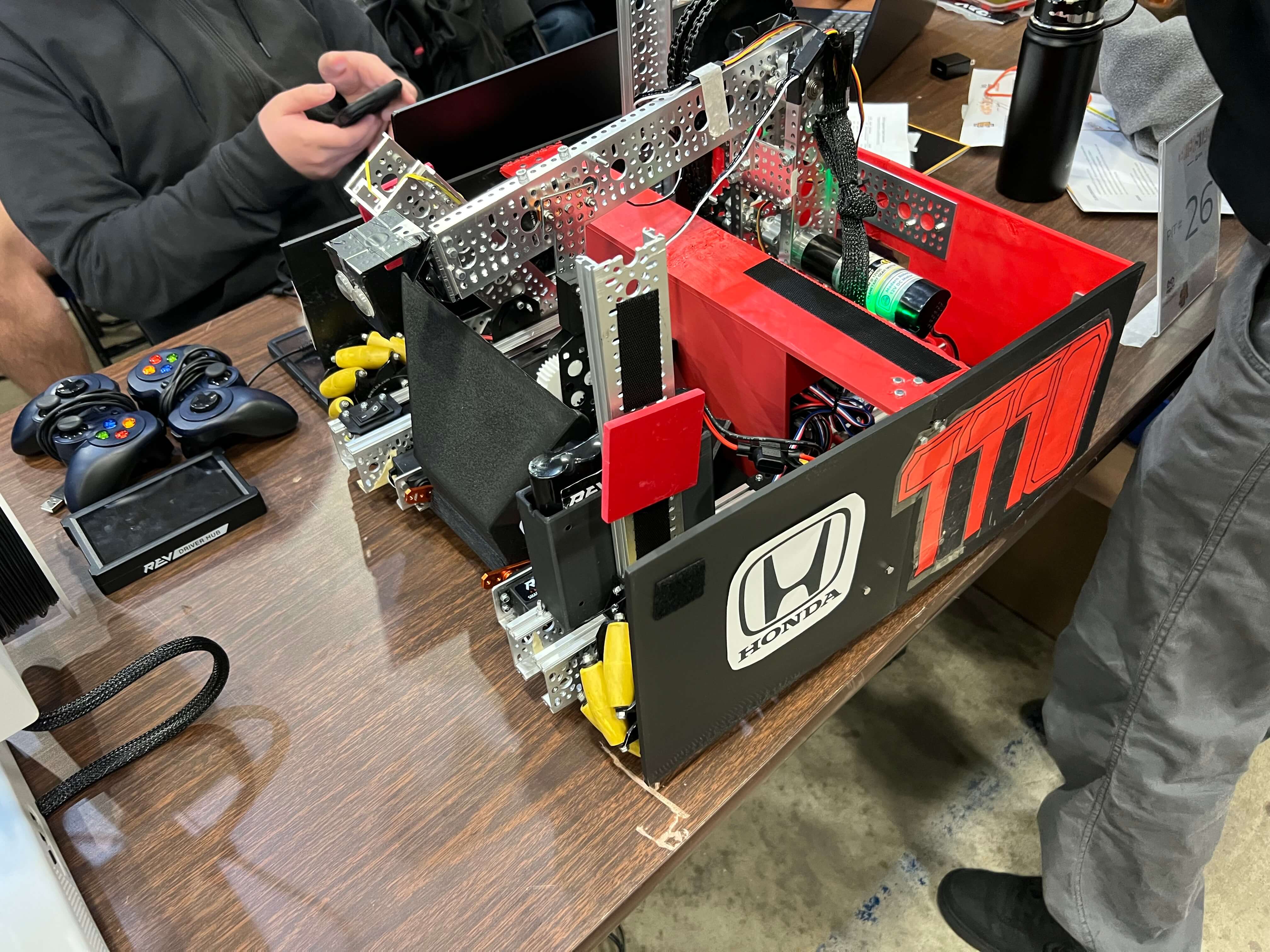
Finished Product
Fully assembled robot.
Our next step was to create our intake. To do this, our 3D printer, Caleb Burd, designed a scoop on Autodesk and a container with wheel attachments to store and vacuum in pixels. We had trouble with the scoop, especially when it came to fitting it on the base, but eventually, we made a working model and managed to fit the scoop on the robot. The mechanism to vacuum the pixels in was harder since the wheels needed to run perfectly, but our team of assemblers and programmers got the job done.
We finished the arm base by programming the arm to take the pixels out of the container and by printing a carbon fiber scoop to ensure it does not break during competition.